

I built my own 7.2kW EV charger and fitted it inside a Zappi enclosure. The 2 aims were simplicity and safety. This article documents the build. I wrote the Arduino software for it and all design files, software and part lists are available on the GitHub page.
Motivation
It costs about £900 in the UK to have an EV charger installed by an electrician. This motivated me to question whether I could build my own since I enjoy these sorts of projects. On researching the topic further I found an open source charger (the EVSE) with good documentation. This gave me the confidence to build my own.
Disclaimer
A word about safety. I’m not an electrician. I’m not allowed to make alterations to my consumer unit. I will have to remove the charger when I leave my house. I’m sure there are countless people that would condemn what I have done here and I can understand why. Building your own outdoor charger which switches 240V 32A could be dangerous if not done right. I have learnt about earthing systems, PEN faults, RCDs, cable current capacities etc. I think I have educated myself enough to have built an adequately safe system. Nevertheless, I welcome constructive criticism and discussion.
Introduction
EV chargers use a simple “pilot” signal to detect when they are plugged into a car and to tell the car how much current it is allowed to draw from the charger. They don’t modify the mains at all, they just switch it on/off to the car via some relays. In addition to this they also incorporate the functionality of an RCD. But to be honest, that’s about it!
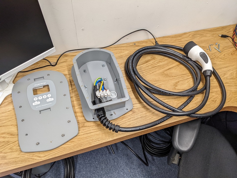
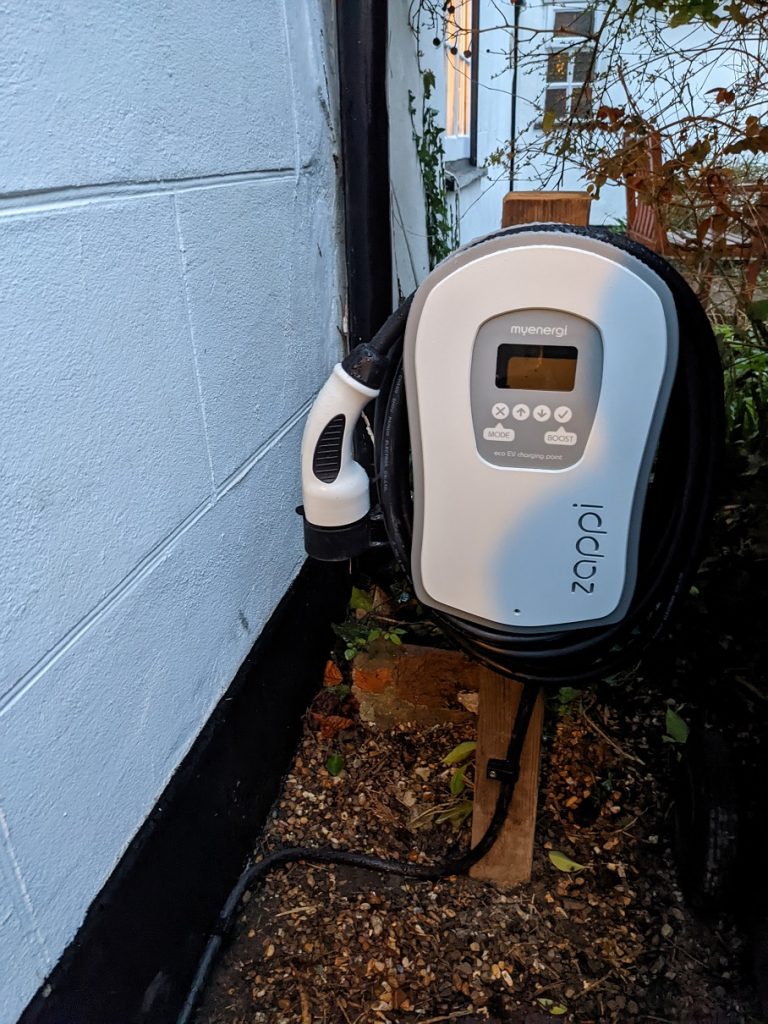
I managed to buy a second hand “showroom” Zappi charger. It came without any of the electronics inside but it gave me an enclosure, cable and plug to work with. I paid £120 inclusive of postage.
I bought 5 metres of 6mm² SWA cable to run from my consumer unit to my desired charger location. I added a 50A MCB into my consumer unit on the non-RCD side and routed the SWA cable using cleats and stainless steel screws.
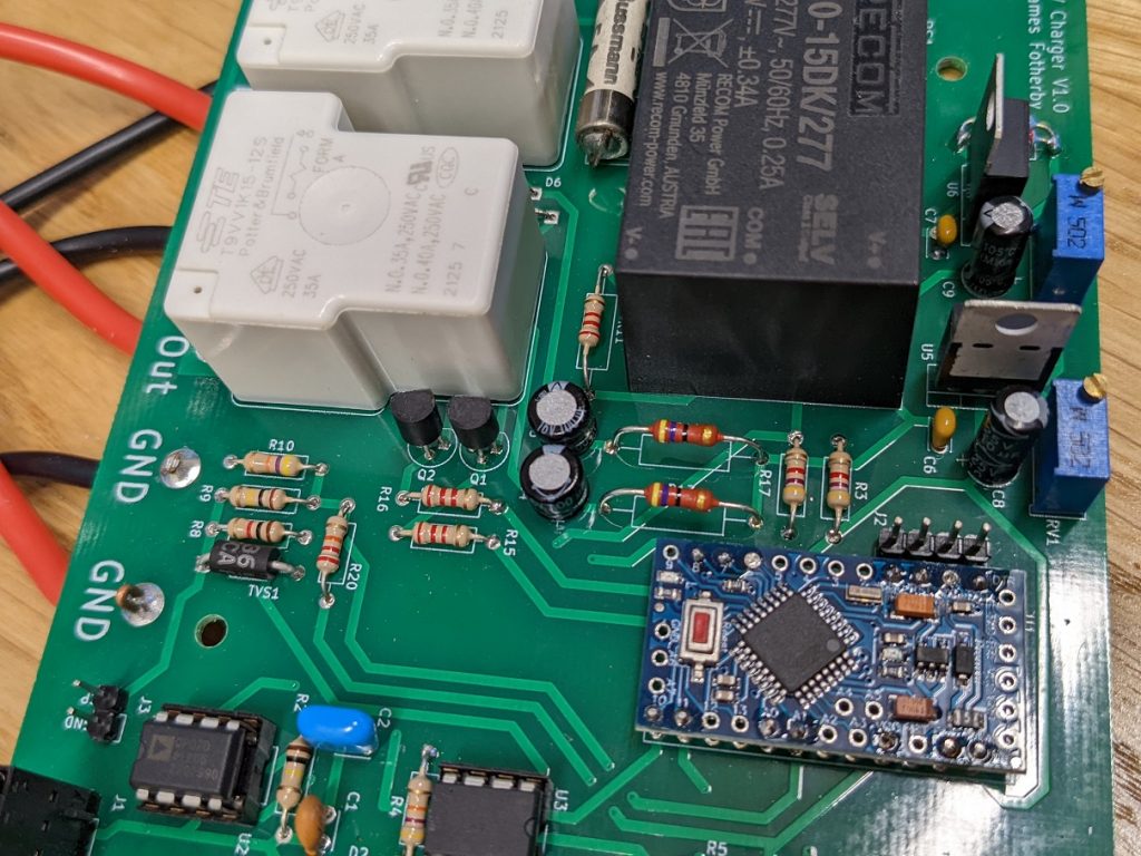
The SWA cable enters the Zappi enclosure through an outdoor water resistant gland. The live and neutral pass together through a current transformer before attaching to the PCB.
Ground Current Detection
One of the most important safety mechanisms to include is a ground current detection system. The chassis of the car is grounded via the earth wire through the charging plug. The earth supply comes from the consumer unit (we have TN-C-S supply).
There is quite a bit of theory behind grounding systems. John Ward has some instructional YouTube videos on the topic which I have watched. He discusses the problem of PEN faults etc. It’s worth spending the time educating yourself about earthing if you are doing any electrical work.
Although unlikely, it is possible for a fault to occur such that a live wire contacts the car chassis. Perhaps it’s pulled loose inside the car somewhere and is touching the chassis or perhaps a wet connector is bridging a path to the chassis.
Either way the live will source current into the chassis which will drain straight to ground (In a TN-C-S supply the ground and neutral conductors are bonded at the consumer unit). The amount of current will depend on the resistance of the faulty bridge. (water is unlikely to allow many amps to flow). Given the chassis is well earthed, it shouldn’t rise up in voltage enough to present a shock hazard to someone that touches it.
Nevertheless, this is a fault situation that should be detected and dealt with. If some water is bridging the live to the chassis perhaps a couple of amps will flow (not enough to trip the 50A MCB for the charger) but enough to cause localised heating and further damage.
So we need to measure current flowing to ground (should be zero in normal operation). If this is more than 20 mA we want to isolate the car by opening the relays. The reason RCDs typically trip at 5-30mA is because this amount of current for a couple hundred milliseconds doesn’t cause permanent injury to humans. I like the wikipedia article on electrical injury.
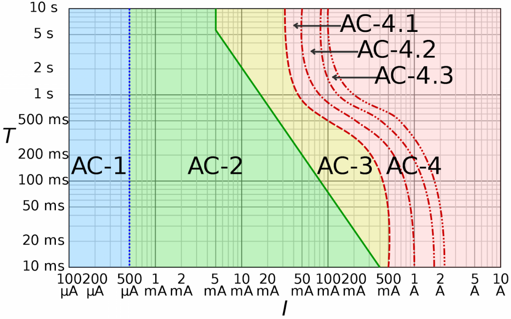
AC-1: imperceptible, AC-2: perceptible but no muscle reaction, AC-3: muscle contraction with reversible effects, AC-4: possible irreversible effects, AC-4.1: up to 5% probability of ventricular fibrillation, AC-4.2: 5–50% probability of fibrillation, AC-4.3: over 50% probability of fibrillation
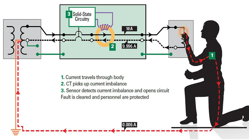
The way to measure current to earth is simple. We employ a current transformer measuring the common mode current of the live and neutral wires. All current should be differential (all current flowing out of the live wire should go through the load and return back through the neutral). If there is a fault and some current does not return then it must be going to earth. This is a common mode current and we want to be measuring this!
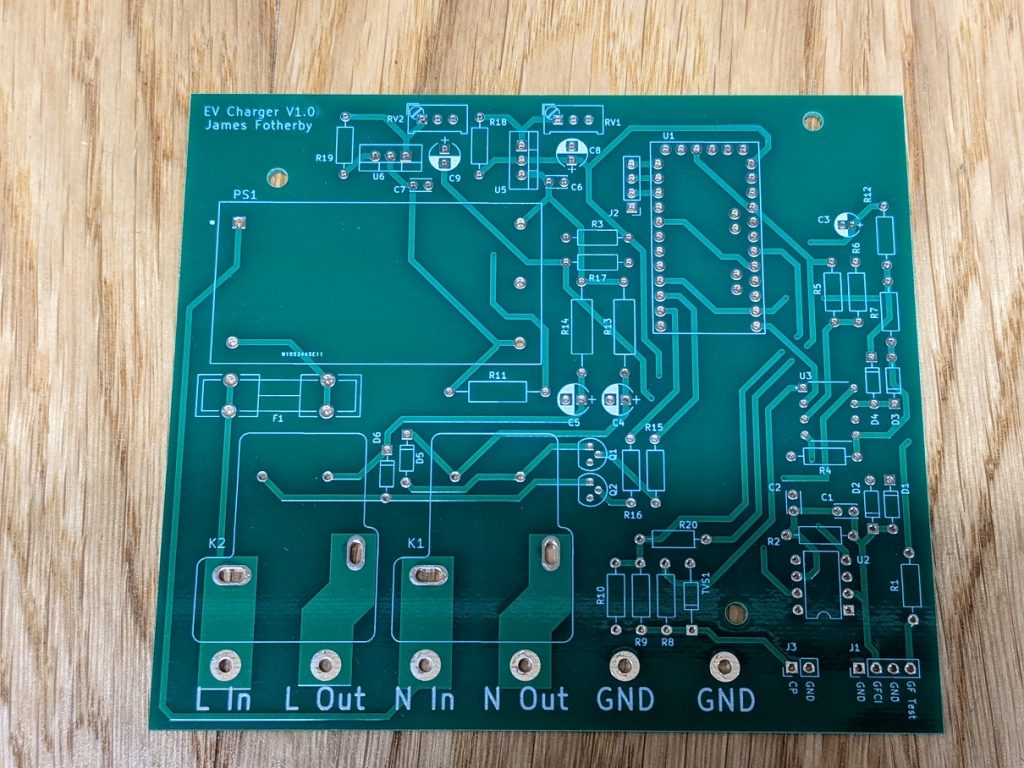
Schematic
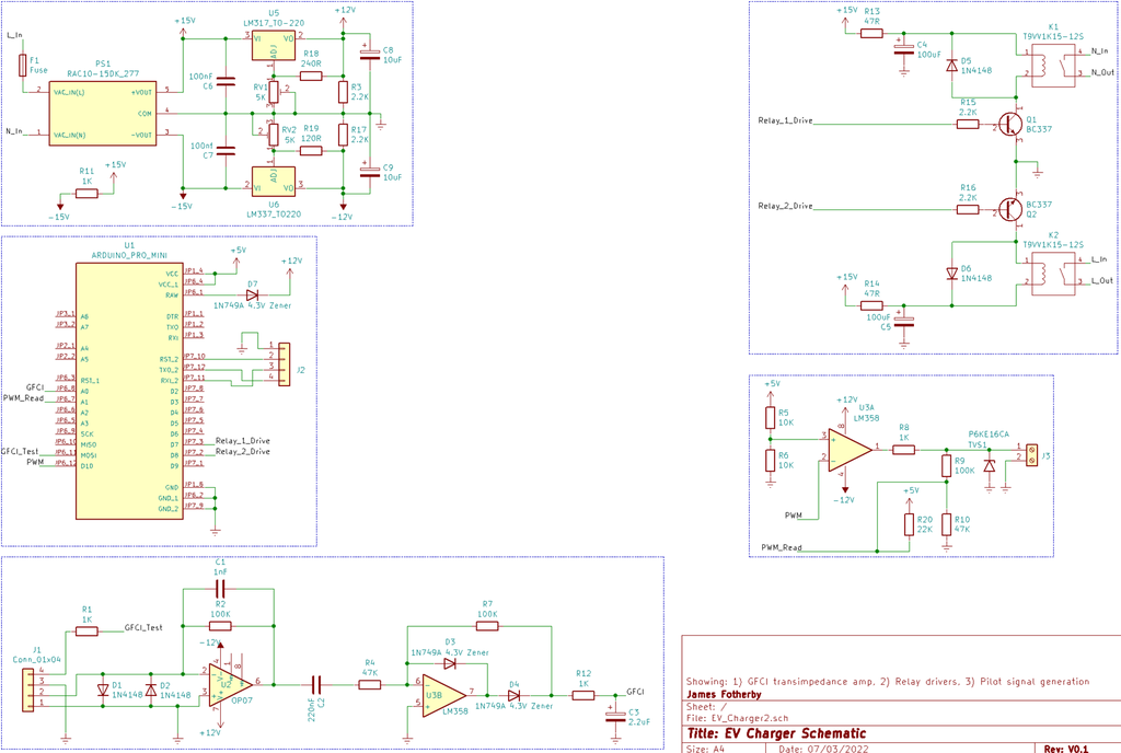
The electronics are necessary for:
- Generating the DC voltages for the arduino, op-amps, relays etc
- Mounting of the 40A 250V L & N relays that switch power to the charging plug
- Generating the +/- 12V 1kHz PWM signal for the pilot
- Amplifying and rectifying the current transformer’s signal prior to the Arduino’s ADC
Power Supplies
I used a RAC10-15DK/277 AC/DC power module. This generates +/- 15 V rails. Adjustable positive/negative linear voltage regulators (LM317 & LM337) produce +/- 12V rails. I was aware the op-amps outputs might not be able to swing all the way to their supply rails so I wanted some flexibility by using adjustable voltage regulators.
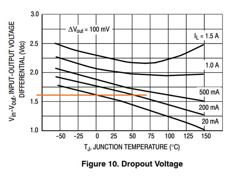
The regulators need a minimum load of about 5 mA to maintain regulation. Therefore R3 & R17 provide a small load for them. The regulators are operating uncomfortably close to their dropout voltages. According to the datasheet the dropout at 20 mA load is about 1.6 V at 0℃ which allows us to up our op-amp rails to about 13.4 V if necessary.
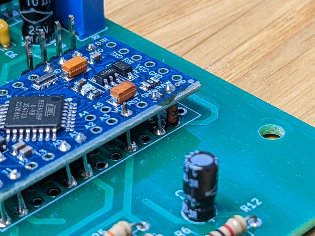
Due to the chip/stock shortages at present, I bought a Pro-Mini module which conveniently housed an Atmega328P Arduino with a 5V regulator. Beware though, this onboard regulator has a max input voltage of 10V so I dropped the regulated 12V using a 4.3V zener diode before supplying it to the RAW input of the Pro-Mini.
Pilot Generation
All communication with the car is done through a single wire referenced to earth called the pilot signal. Read here and here for descriptions on how this signal works. In a nutshell, depending on whether the car is connected/ready to charge etc, the car places different resistances on the pilot signal. This causes changes in the voltage of the pilot signal.
An LM358 Op-Amp takes a 0-5V PWM signal from the Arduino and converts it into a +/-12V signal to form the pilot. Easy.
We use a voltage divider network to condition the pilot voltage before feeding it into an ADC channel for measurement. A 13.6 V 600W bidirectional TVS just ensures no whacky voltages are ever experienced on the pilot wire.
Relay operation
I initially thought I ought to share the load on the SMPS between its 2 power rails. So one relay would be powered by the +ve rail and the other by the -ve rail. However doing this added a couple of extra parts to the design and slightly increased the overall complexity. For the sake of simplicity I kept both relays powered from the +ve supply rail and this has ended up working absolutely fine.
The T9VV1K15-12S relay specifications report a coil holding voltage of only 4.7V. This can conserve a lot of power. You can see from the schematic, we charge 100uF capacitors from the +15V rail through 1W 47R resistors (R13 & R14). When the relays are activated they initially but briefly get 15V. But the steady state voltage decays to about 9V. I should have gone for 68R or even 100R resistors for even more power conservation.
The BC337 transistors get about 2 mA of base current through the 2.2K resistors. This is adequate to sufficiently switch the transistors.
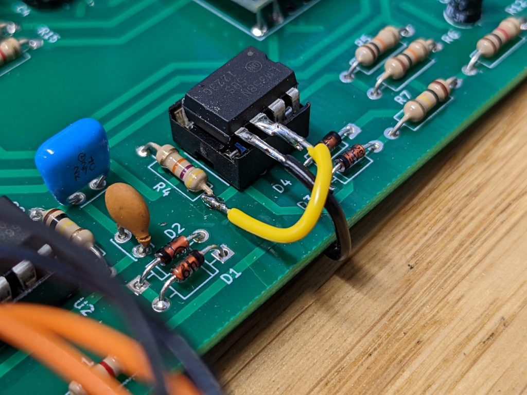
Current transformer
A current transformer is analogous to a voltage transformer. We put 1 turn on the transformer primary by passing the live and neutral once through the ferrite core. On the secondary we have many turns – 100s of turns. A current on the primary is therefore induced onto the secondary albeit at a magnitude proportional to the turns ratio. If we have a 20mA current on the primary and a 1:400 turns ratio we’ll have a 50uA secondary current.
Just like a voltage transformer doesn’t like to be short circuited. A current transformer doesn’t like to be open circuited. The best method to measure the secondary current is to use a transimpedance amplifier.
U2 is the OP07 low-offset op-amp. The V+ terminal is grounded and in this configuration the output will swing around to always keep V- at the same voltage as V+ (ie. 0 V). Imagine if the current transformer forces 50 uA towards the V- terminal of U2. The op-amp will reduce its output voltage to -5 V so that the 50 uA is entirely pulled through R2 (V = I x R = 50uA x 100K). Hence the V- terminal is kept at exactly 0 V. So you can see in this configuration that currents from the transformer are converted into voltages at the output of the op-amp. C1 just helps to reduce the gain at high frequencies and act as a low pass filter. D1 and D2 stop any voltage excursions beyond about 0.7 V should the transimpedance amplifier get saturated.
We probably didn’t need the low-offset features of the OP07. C2 removes any DC bias anyway. U3B is configured to act as a further amplifier stage and precision rectifier. The 4.3 V zener diodes used clip the output to a ~4 V maximum as well. R12 and C3 add a final low pass filter before going to the ADC channel.
All in all, AC currents from the ground fault current transformer are converted into voltages, amplified, rectified, limited and filtered before being passed to the Arduino ADC for measurement. This circuitry worked and made sense to me so I went with it. But you could probably simplify it further.
PCB Design
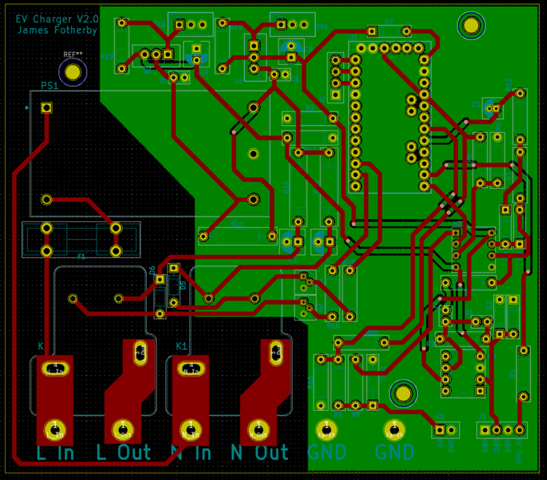
I used KiCad to design the PCB. I have settled on KiCad because it is open source and you can do multi-layer PCBs if you need to. SnapEDA is key for importing PCB footprints for parts. There is not much to say about the PCB design. I kept a 4mm clearance around high voltage traces. I ordered the PCBs from PCBway who get them back to you in about 1 week!
Assembly
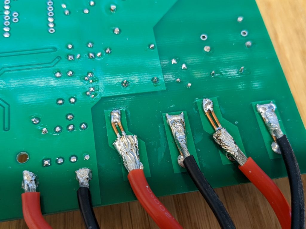
I soldered up the PCB with the parts I got from Mouser. I realised I got one op-amp’s pins flipped wrong on my design so you can see an ugly little correction to fix that. I also didn’t realise the Pro-Mini’s regulator can’t handle >10 V so I burnt one out whilst adjusting the supply rail voltages. Lucky I had bought a pack of 3 Pro-Minis. I’ve added a 4.3v zener diode after this mistake to drop the voltage down before feeding it to the Pro-Mini. I have corrected these problems on the schematic and PCB on github and called the PCB V2.0.
Software
Hopefully the code is commented well enough to make sense. Find it on the GitHub repository.
There is a self test coil on the current transformer. The software performs a self test by putting a 50Hz 5 mA square wave through the 5-Turn test coil. This essentially simulates a 25 mA ground fault. We time how long it takes for the fault to be detected. If the fault is detected within 100 ms the test is passed.
Testing
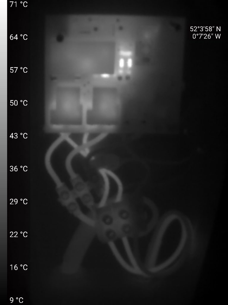
I took some thermal images of the device under load. The relay resistors are dissipating 900mW (They’re 1W rated) which gets them to about 60 celsius above ambient. The wiring and terminal blocks are fine with nothing hotter than 15 Celsius above ambient.
The following embedded video demonstrates the device working.
The following RCD test video is done by connecting a 10K resistor (24 mA ground fault current) from live to ground. It causes the device to immediately interrupt the charging process and trip out. That proves successful RCD functionality.
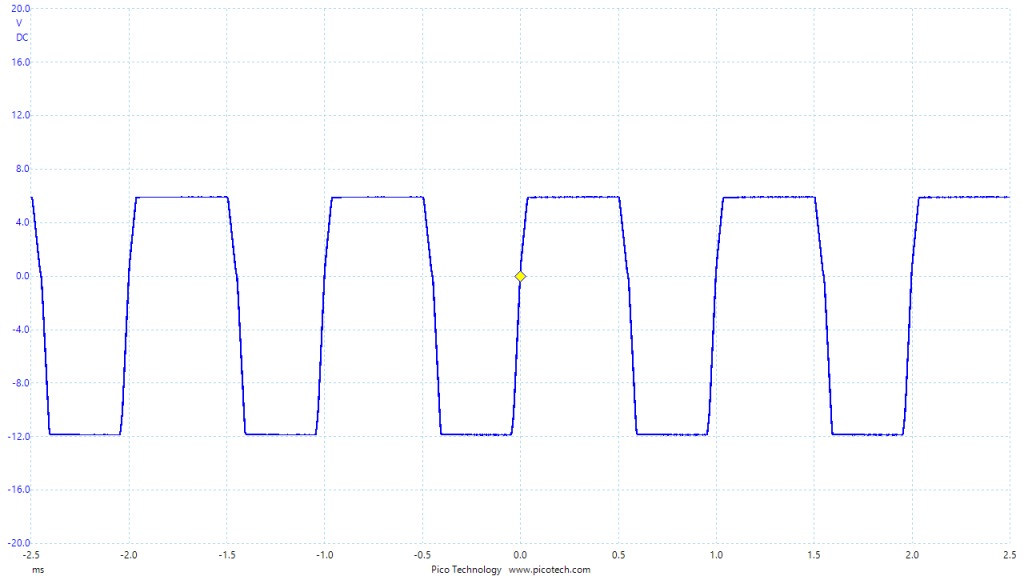
Out of interest, I measured the voltage across the relay coil when actuating. The blue trace is the coil voltage and the red trace the switched AC output. It seems to take about 5 ms to actuate the relay. The contacts obviously bounce a little bit after coming together.
Likewise the release of the relay seems to take about 10 ms.
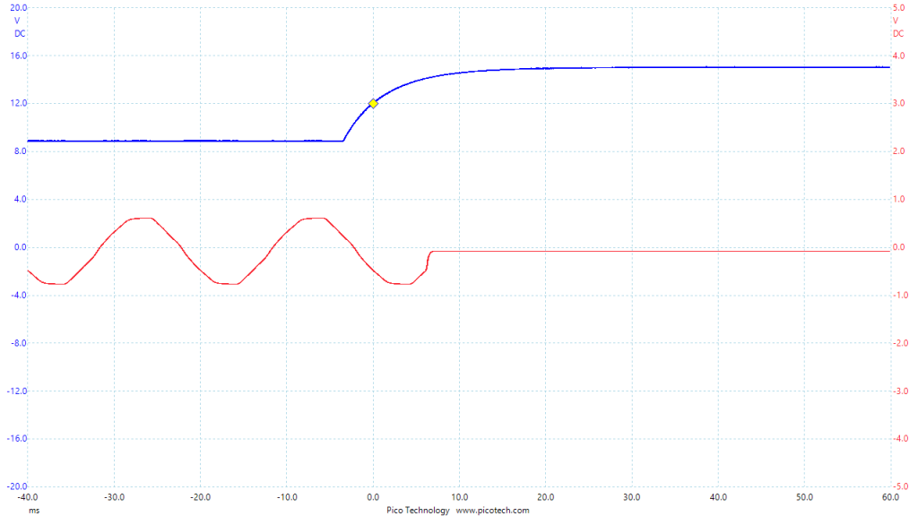
The pilot voltages are exactly as they are supposed to be. The SAE_J1772 specifications do allow +/- 0.5V from the +12V, and +/- 1V on the +9V, 6V and 3V levels so we’re comfortable.
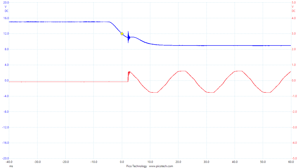
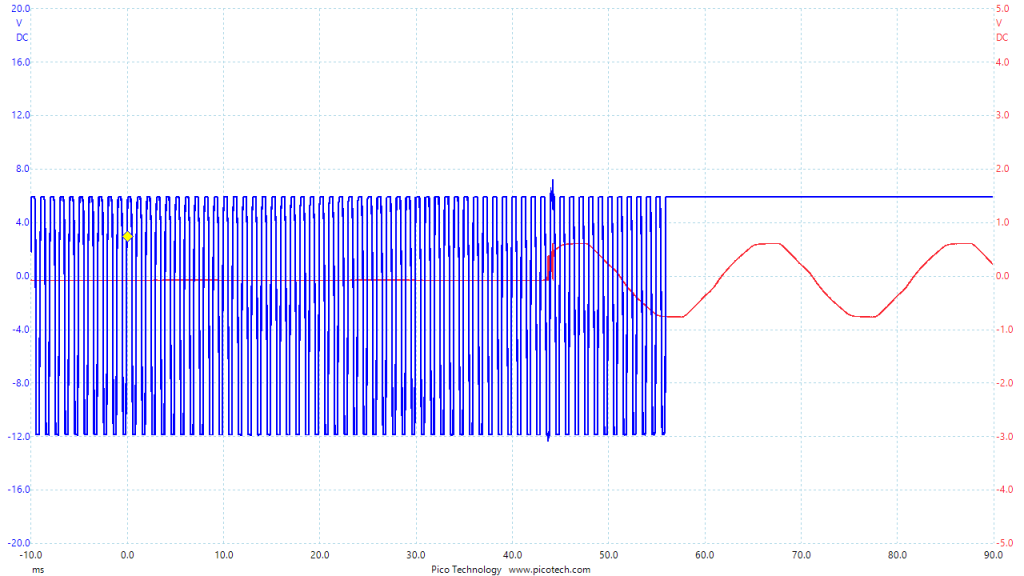
This trace shows what happens when a car is detected. The +12V DC pilot is pulled down by the car’s 2.74K resistor. After a 200ms hiatus, the software switches to “State B” and starts the 1kHz PWM.

Here’s the pilot when the car is charging. -12V to +6V. The software is measuring the voltages at the centres of the low and high regions.
It was important to test the ground fault detection circuit. I tested it to trip at 6 mA. Here’s a trace to show the speed of a trip when a 22K resistor is connected to earth across the 240V live resulting in an 11 mA current. The detection time is 12 ms (start of the AC waveform to the rising edge of the blue waveform. Hence with the 10 ms relay release time the power will be cut in 22 ms. That’s within the EV charger national specifications.
Conclusion
I’m delighted with the end result. It doesn’t have an LCD screen but my car tells me how fast it’s charging and allows me to configure charging times etc. I don’t need any smart functionality. I have a smart meter so I know how much electricity I’m using etc too.
Total cost? Well about £200. Plus several days of hard thinking, soldering and coding. Good fun though. Let me know what you think.
Post Publication Updates
This project was featured on Hackaday. There are quite a few (mostly negative) comments about this project commenting on the safety of this implementation. This is a summary as of 2/5/2022 of the feedback.
1) The soldered connections on the PCB are inadequate – Ok, I agree with this. A 40A terminal block would be much better. I should have done that. Is there any appreciable risk of those solder joints melting before the 50A MCB trips? I took some thermal image pics of the system operating at 30A and there are no hot spots in the solder/wiring/connections. The flimsier looking terminal block actually came with the Zappi enclosure so it implies the terminal blocks are appropriately rated.
2) Bad choice of relays – according to the datasheet, the relays used in this project are for EV chargers and can handle 250V 40A. EV cars soft start/stop their charging so the relays don’t have to connect/interrupt under load unless due to a fault condition. If you look at teardowns of some commercial chargers (eg. Zappi) you’ll find separate L&N single pole relays just like I have used. But, I agree having a dual gang relay so the L&N are mechanically linked does sound better. I have measured the power factor of the car charging (albeit when charging from a 13A socket) using a plug-in power meter and it reports a power factor of 0.95. So I think the car does present a resistive load. Logically, car manufacturers must have to ensure their onboard SMPS chargers have good power factor else the extra currents would cause problems in domestic setups, I agree.
3) Unsafe to use an Arduino (ATMEGA328P). I think you technically need special authorisation from atmel to use this chip for automotive or safety critical applications. I like the suggestion of incorporating a watchdog timer to guard against hanging. I’ll add that. And I like the suggestion [steaky] of having to regularly toggle a pin purposefully to maintain engagement of the relay so they’d open by default during an error. Is that actually done in commercial chargers? It’s not done by the EVSE. If an unexpected reset occurred the relays would open in this implementation.
4) Should be a type B RCD – I think this is the main point from everyone. That the RCD functionality is inadequate. I essentially copied the EVSE RCD design, which I thought was a acceptable approach. What do people think of the EVSE RCD? The requirement for EV chargers to have a Type B RCDs is a relatively new regulation brought into play in the last few years. This forum discusses the change prior to the standard being introduced. Type B RCDs can detect DC ground fault currents (not such an easy thing to do), this is a good article explaining everything about them and how they work.
How safe is adequately safe? 5 years ago the Type A RCD incorporated in this project would have been deemed adequate. Currently I’m ok going with the safety standards of 5 years ago. I’m trying to address the main safety points here, after which you encounter rarer and rarer eventualities that require some extremely unlikely situations to occur. People say my house is going to burn down. I think that’s a bit melodramatic. For starters the unit is mounted outside. Will it void my car warranty? I don’t think so because the AC power isn’t altered by the charger. This is a bespoke implementation which admittedly doesn’t meet the stringent regulatory requirements that commercially produced chargers must. For my situation, I’m ok with that.
Summary of community recommendations:
- Terminal blocks on the PCB
- Use a dual gang relay
- Add watch dog timer – DONE
- Add Type B RCD Functionality
- Could add smart functionality – eg Power draw sensing, WiFi etc
14 responses to “Electric Vehicle Charger”
-
I realised an EV charger based on your PCB. I solved the problem of Watchdog, I added a display and a selector for max charge current. I also added a power consumption measurement and an enable signal from my domoticz installation. It is based on my own software and work perfectly for more than 6 months now.
Thanks for your PCB design.
-
I’m very pleased to hear about your successful implementation. Do you have a link to the software? Do you have any pictures to show? I did add a watchdog to this implementation after community recommendations.
-
I don’t know how to send picture and files. Could you please tell me?
-
Could you please tell me how to send pictures and files?
Thanks
-
Hi
Im a student and we are trying to build this charger but we wanna add some option
Do you have time to talk in google meet
Please send me a message
Mohammadmahdivahid81@gmail.com
-
-
-
Hi,
Could you tell me how I can upload pictures and files of my charger?
Thanks-
Hey Maillard,
You can upload to “Google Drive” and share folder link here.
I’m curious about your contributions to this project.
Thanks for improvements!
Have a nice day.
Thanks.
-
-
James Fotherby’s comprehensive guide to electric vehicle chargers is a well-crafted resource for individuals navigating the world of EV charging. The article covers various aspects, from types of chargers to installation considerations, offering readers a holistic understanding of the charging infrastructure. In a time of rapid technological advancement, this guide serves as a valuable reference for both novice and experienced EV enthusiasts.
-
Look in to a PWM based coil economizer circuit. The MPS MPQ6519 is really nice and would let you drive full current and then fall back to a lower holding current, utilizing the inductance of the coil itself as part of a switching converter. It won’t get hot like the resistor approach, and you won’t need anywhere near as large a capacitor either.
-
Nice. I like that although it undoubtably adds complexity and you’ve got ask the question whether a 1W saving whilst charging is worth the added effort…
-
-
Kia eNiro. Nice car, I got one as well.
If you dont have it yet, switch to octopus go, dirt cheap electricity for 4 hours at night
-
Oh I did that years ago and it has been brilliant.
-
-
Hello,
Very cool project, well documented. Obviously you did a lot of research, and your design looks sound overall.
To reinforce the comment about safety done in Arduino, that’s the major point where I would recommend you revise your design, or discourage someone from reusing this design.
Implementing any functional safety in embedded software (or software) is doable, but it is extremely difficult. For a good reason: software is executed on hardware, so to guarantee it will behave like you expect, you need to prove that the hardware (ATMega in your case) AND the software (code you wrote, libs you used, compiler, linker, etc… EVERYTHING!) has been designed with safety in consideration. Let me give you a clue: unless you are an expert with years of experience in this domain, don’t even think it is feasible.
That’s why without going through all these steps, in the eyes of safety approval bodies any piece of firmware or software is assumed to fail.
Instead, what I would recommend is that you implement a full hardware safety: this should be easy, since you already have the transformer and signal conditioning (opamps). You just have to use the output of your circuit to take action in case of a fault.
For example, send the signal to a clampling comparator that will open the relays and stop the pilot signal (as needed).
If you were to submit such a circuit to a safety lab, it would be much easier to make your case.Last note, I am not sure if you added any thermal protection? Validating the temperature in use is great, but taking action in case things go wonky would be even better. Again, full hardware solution would be best. It can be very simple if considered early on.
I hope you will find my comment constructive. Safety is not easy but is not impossible neither. Most important is to test to ensure everything works as expected.
Winshing you the best.
-
Hello,
Thank you very much for your comment, it’s incredibly informative. Everything you have said makes a lot of sense and I agree that implementing all of the safety features in hardware wouldn’t be that challenging. I can see how hardware implemented cut-outs are more robust and safe. I like the idea about thermal safety too.I have learnt masses from the comments people have left regarding this project. I’d incorporate most of their suggestions if I did it all again.
James
-
Leave a Reply