I bought 16 LiFePO4 cells from Fogstar for an off-grid solar battery system . Each cell has a nominal voltage of 3.2 volts and stores 314 Ah equating to 1 kWh per cell. Connecting the cells in series builds a 52 volt 16 kWh battery pack costing £1200 (October 2024). Here’s the whole system:
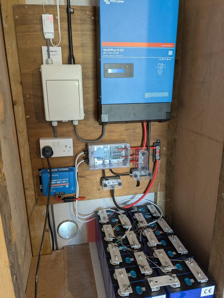
This webpage is dedicate to discussing the custom battery management system:
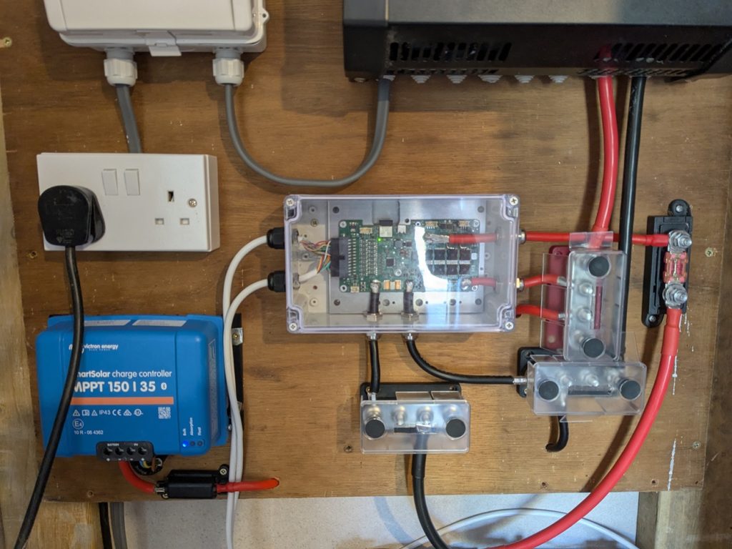
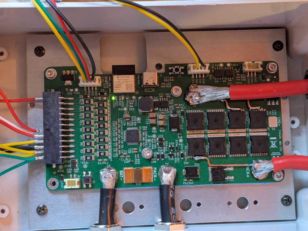
LiFePO4 batteries can perform more cycles than lithium-ion batteries. Apparently these cells can do 8000 cycles between 3.65v and 2.5v before they reach 70% of their design capacity. I’d be chuffed if they achieve half that.
Lithium based batteries need a battery management system because permanent damage occurs immediately if a cell gets overcharged or over discharged. A BMS is an electronic circuit that must do these functions at a minimum:
- Measure the voltages of each cell in the pack (16 in this case)
- If any cell falls below its minimum safe operating voltage (2.5 volts) the BMS must disconnect the load on the battery to prevent that cell being discharged anymore.
- Likewise if any cell in the pack rises above its maximum safe operating voltage (3.65 volts) the BMS must disconnect the charger to prevent further rises in this voltage.
- Maintain balance of all cells in the pack so their voltages are all about the same.
A few more useful functions a BMS can perform:
- Pre-charge any load capacitance through a resistor before connecting the battery to the load properly.
- Measure currents in/out of the battery and integrate this over time to get accumulated charge. This allows for better state of charge (SOC) and state of health (SOH) calculations.
- Overcurrent protection and temperature monitoring for safety
For a month my voltmeter and I were the BMS for the pack. I diligently measured the cell voltages and have been pleased to find that the cells have all stayed balanced to within 10 millivolts of one another which is the resolution of my voltmeter. Nevertheless managing a £1200 battery pack this way is not relaxing.
I couldn’t find a good off-the-shelf BMS but instead discovered the OpenBMS project by Martin Jäger. I downloaded the Kicad files, ordered the parts from mouser and the PCB from PCBway and assembled the board:
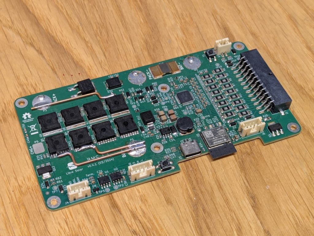
The PCB combines the BQ76952 BMS chip by Texas Instruments with an ESP32-C3 module. I want to have all the battery metrics stored in a time series database (InfluxDB) on my server and remotely viewable via grafana. An ESP32 connected to a local WiFi network should enable this to happen. This is what I’d like to monitor:
- Individual cell voltages
- Pack voltage, pack current and accumulated charge
- Estimated state of charge (0-100%) and remaining capacity in kWhs.
- Individual cell state of health and capacity estimations over time
- Individual cell cumulative balancing time
I thought I’d spend the rest of this article discussing:
1) The OpenBMS hardware
It’s a very nicely designed PCB and you can read all about it on the dedicated website. This is how it is connected up to a 16 cell pack:
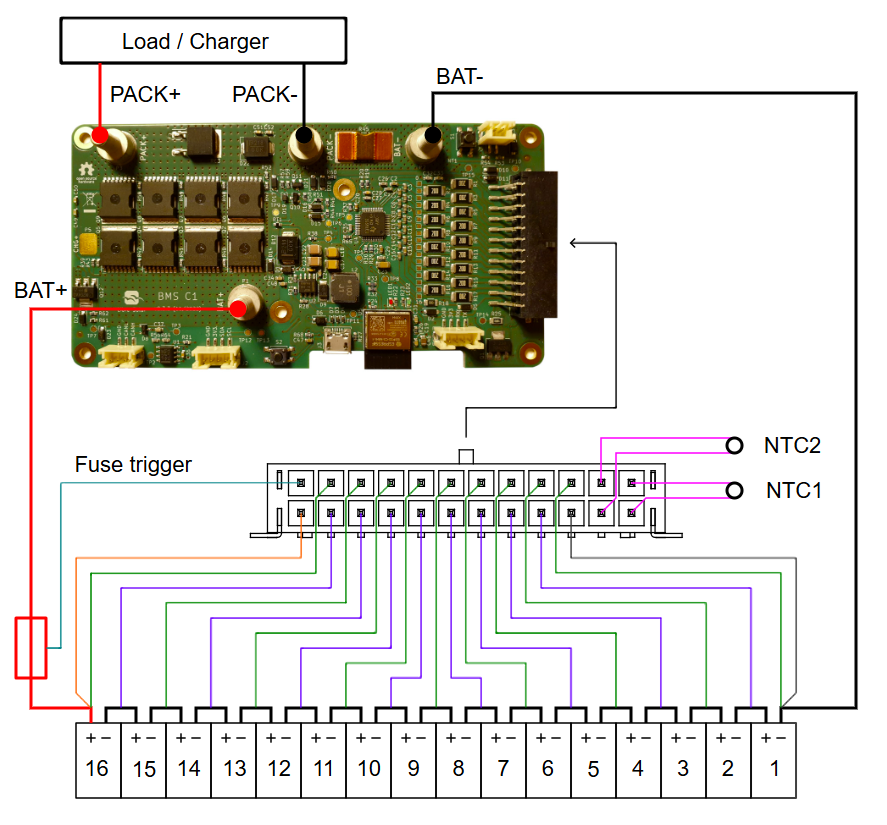
The specifications suggest that the board can pass 100A of continuous current. Given I am powering a 5000W Victron Multiplus-II GX inverter this is adequate for a 52v battery system. It’s a 4-Layer PCB and below is a picture showing the top and bottom copper layers. 2oz copper pours should be used.
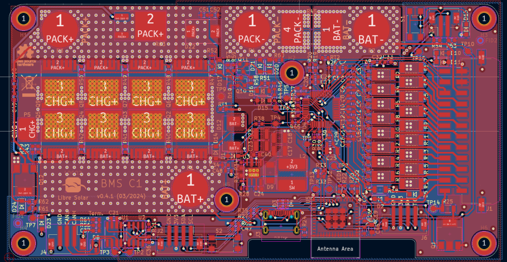
At 100A there will be a fair bit of heat generated by any resistances:
- Each MOSFET has an Rdson = 1.2mOhm. The 4×2 array will total 600uOhm of series resistance
- The current shunt has a resistance of 300uOhm
- The PCB traces, vias and connections will add another ~1mOhm
Altogether 2mOhm at 100A generates 20 W of heat. I think the power connections into and out of this PCB are one of its design weaknesses. I’d like to see screw terminals with legs that carry the currents directly to each of the 4 copper layers in the PCB. Such as these:
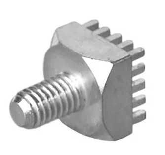

A through hole solution like above would be much more robust. I have found these 180A rated terminal blocks on mouser that I think would work well.
I have soldered 6 AWG wire onto the 10mm exposed pads. The connections feel secure but I am not happy with this solution! I have half a mind to make my modifications to the PCB and rebuild it. If I were to do this I would make these improvements as well:
- I found the hidden solder pads on the ESP32-C3 module difficult to solder. I had to reflow the whole module a second time because it initially hadn’t soldered properly in my oven. I’d prefer a module with side pads like the ESP32-C6-WROOM-1U-N8 has.
- I’d like some exposed copper pour along the MOSFET pins for a strip of copper wire soldered on to the PCB. This would aid current handling.
Overall the hardware is terrific! If you need a BMS that can handle higher currents you’d have to add more MOSFETS and probably use a bigger current shunt or an external one. I’ll use what I have got for the time being and consider making my improvements at a later date.
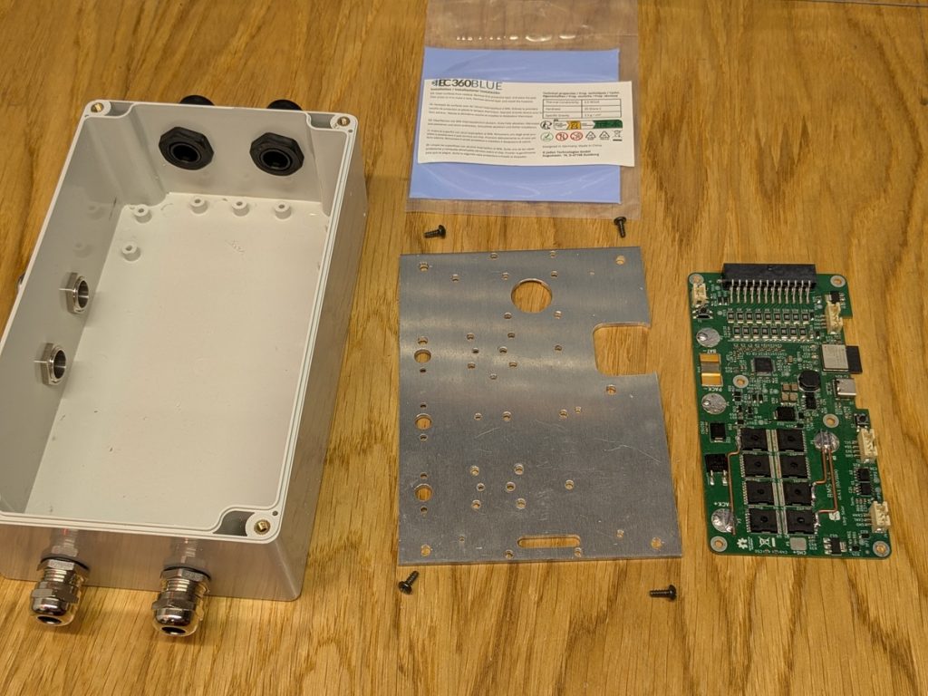
I’ll mount the board on a thermal pad and aluminium plate inside an air tight enclosure. Enclosures are key for stopping corrosion, dust and insects causing any damage to the delicate electronics. How much heat the board will be able to dissipate inside this enclosure is something I shall discover later.
I wanted to write my own software so that is what I have done:
2) Configuring the BQ76952
The BQ76952 is a autonomous BMS chip. Meaning that you could program all the configuration settings into its permanent memory on the manufacturing line and not require a microcontroller on your BMS board. It has a 207-page technical reference manual which is invaluable for understanding and configuring all of its settings. You can interface to the chip via a few communication protocols but the OpenBMS uses I2C. I have written the BQ76952 Arduino library which makes it easy to read and write to the registers.
Here is some example code showing the main settings needed to have the BQ up and running as a BMS. We’ll refer to the code as we explain the settings later.
// Demo code to show basics of BQ library

#include <BQ76952.h>

#define I2C_SDA_PIN         8
#define I2C_SCL_PIN         9

BQ76952 bms;

void setup() {
  Serial.begin(115200);
  bms.begin(I2C_SDA_PIN, I2C_SCL_PIN);
  bms.setDebug(true);

  bms.reset();
  delay(100);

  // Configure the BQ76952 just the way we like it:
  bms.setConnectedCells(16);

  // Set Cell voltage protection to 2.50 - 3.50 volts
  bms.writeByteToMemory(CUV_Threshold, 50);
  bms.writeByteToMemory(COV_Threshold, 69);

  // Set OCD1 to 60mV across shunt (200A)
  bms.writeByteToMemory(OCD1_Threshold, 30);

  // Set SCD to 80 mV (265 A)
  bms.writeByteToMemory(SCD_Threshold, SCD_80);

  // Enable CUV, COV, Short circuit and OCD1 protection
  bms.writeByteToMemory(Enabled_Protections_A, 0b10101100);

  // FET thermistor on DCHG. Enable FET + internal temp protections
  bms.writeByteToMemory(DCHG_Pin_Config, 0b00001111);
  bms.writeByteToMemory(Enabled_Protections_B, 0b11000000);

  // Report in centiamps (10mA),configure for 300uR shunt [default: 1mR]
  bms.writeByteToMemory(DA_Configuration, 0x06);
  bms.writeFloatToMemory(CC_Gain, 24.92267);
  bms.writeFloatToMemory(Capacity_Gain, 7433474.88);

  // This enables the Pre-discharge function (1600 ms, 2.5 v delta)
  bms.writeByteToMemory(FET_Predischarge_Timeout, 160);
  bms.writeByteToMemory(FET_Predischarge_Stop_Delta, 250);
  bms.writeByteToMemory(FET_Options, 0x1D);

  // Configures balancing parameters
  bms.writeIntToMemory(Cell_Balance_Min_Cell_V_Relaxed, 3300);
  bms.writeByteToMemory(Cell_Balance_Max_Cells, 8);
  bms.writeByteToMemory(Balancing_Configuration, 0b00000010);

  // Disables SLEEP, slow measurement speed when balancing to 1/8th
  bms.writeIntToMemory(Power_Config, 0b0010100010110010);

  // Exits manufacture mode. Allows BQ to enable FETs subject to protections
  bms.writeIntToMemory(Mfg_Status_Init, 0x0050);
  bms.setFET(ALL, ON);
}

void loop() {
  delay(200);

  Serial.print(bms.getCellVoltage(1)); Serial.print(", ");
  Serial.print(bms.getCellVoltage(2)); Serial.print(", ");
  Serial.print(bms.getCellVoltage(3)); Serial.print(", ");
  Serial.print(bms.getCellVoltage(4)); Serial.print(", ");
  // etc.

  // Stack voltage
  Serial.print(bms.getCellVoltage(17)); Serial.print(", ");

  // Pack voltage
  Serial.print(bms.getCellVoltage(18)); Serial.print(", ");

  Serial.println(bms.getCurrent());
}
We want to configure all the settings to make it suitable for a 16-cell 16 kWh 52v LiFePO4 battery pack. Lets talk through the list of all settings I have chosen:
- Cell undervoltage and overvoltage settings
- Overcurrent protection
- Temperature protection
- Current reporting and gains
- Pre-discharge functionality
- Cell balancing configuration
- Exit manufacture mode
2.1) Cell undervoltage and overvoltage settings
We tell the BQ how many cells are connected. We then enable SCD, OCD1, COV and CUV by setting the 0-7 bitmask appropriately:
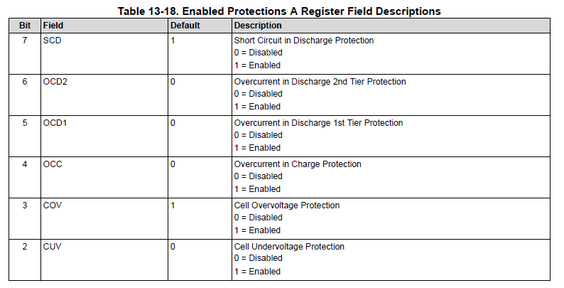
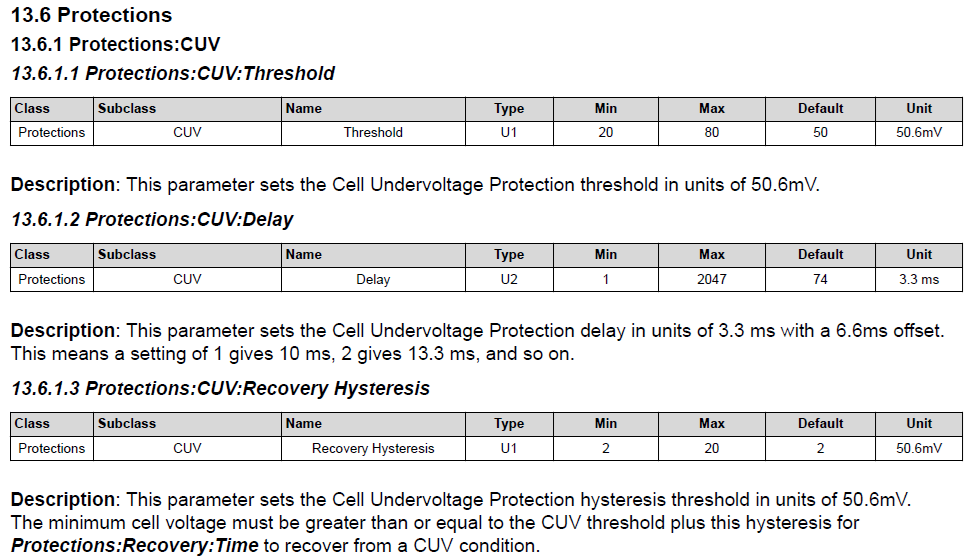
You can see below that CUV and COV are written in units of 50.6 millivolts so 50- 69 corresponds to 2.5 – 3.5 Volts. There is also a configurable delay and a recovery hysteresis which we shall leave at their defaults of 250 milliseconds and 100 millivolts respectively for both CUV and COV.
2.2) Overcurrent protection
The BQ has a number of different current protection features:
- OCC – Charging overcurrent – Disabled
- SCD – Short circuit protection – Enabled
- OCD1 – Tier 1 overcurrent detection – Enabled
- OCD2 – Tier 2 overcurrent detection – Disabled
- OCD3 – Tier 3 overcurrent detection – Disabled (by default)
We disabled OCC earlier because our solar system is only 2 kW peak. The inverter can peak briefly at 9000W which equates to ~180A of discharge current. Makes sense to therefore set OCD1 to cut the load if 200A is exceeded. This is equivalent to 60 mV across our shunt and OCD1 has a default delay of 10ms which seems reasonable.
We want SCD and we did enable this. The BQ defaults are 15 us detection time, 5 second recovery time and we need to set the threshold to trip at. So lets trip at a shunt voltage threshold of 80 mV which equates to 265 A.
2.3) Temperature protections
  // FET thermistor on DCHG. Enable FET + internal temp protections
  bms.writeByteToMemory(DCHG_Pin_Config, 0b00001111);
  bms.writeByteToMemory(Enabled_Protections_B, 0b11000000);
Temperature protection is pretty key. The BMS could have quite a large amount of current flowing through it. All of the components can handle the currents but the limiting factor is how hot the PCB gets. These commands enable the temperature protections at their defaults of 80 degrees cut-out and 65 degrees Celsius cut back in.
2.4) Current reporting and gains
bms.writeByteToMemory(DA_Configuration, 0x06);
bms.writeFloatToMemory(CC_Gain, 24.92267);
bms.writeFloatToMemory(Capacity_Gain, 7433474.88);
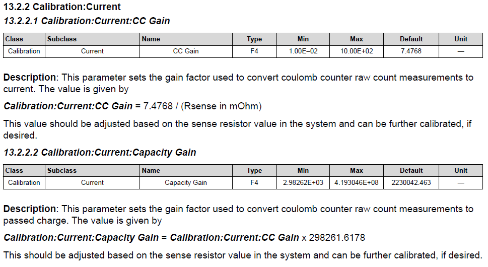
These lines tell the BQ to report current in units of 10 mA. This is necessary because a 16-bit current reading can then range between -327.68 to +327.68 A. We adjust the gains in the device because the default gains assume a shunt resistance of 1mR. The OpenBMS uses 300uR.
2.5) Pre-discharge functionality
A 5000W inverter like the Victron Multiplus-II GX has a massive amount of bulk capacitance. Perhaps about 10mF. On connecting a 48 volt battery an enormous current flows producing a nasty loud spark. It’s not great for the inverter’s capacitors, the batteries or the switches in the BMS. In fact this amount of capacitance being charged dissipates 12 joules of energy in the resistance to the capacitor. 12 joules is the same amount of energy as 1 kg dropped from 1.2 m.
The bulk capacitance charges up within a couple RC time constants. Without a pre-charge circuit there’s only about 5 milliohms to the inverter’s capacitors. An RC time constant is ~50 us. Dissipating 12 joules (ie. stopping the 1 kg weight) in 0.1 milliseconds is going to pop or shatter something!
To avoid this problem the openBMS has a pre-discharge circuit. This first connects the battery pack to the output of the BMS through a 40 ohm resistor. This charges the bulk capacitance controllably before the main MOSFETs are switched on. The BQ76952 can be configured to pre-discharge for a fixed amount of time (eg 1500 milliseconds) or until the output voltage has risen to within a certain delta of the battery voltage, or both. I’ve decided to go with both.
The 40 ohm resistor will still dissipate the 12 J of energy but the RC time constant now becomes 400 milliseconds. If you look at the datasheet for the resistor it shows this graph for the pulse power rating:
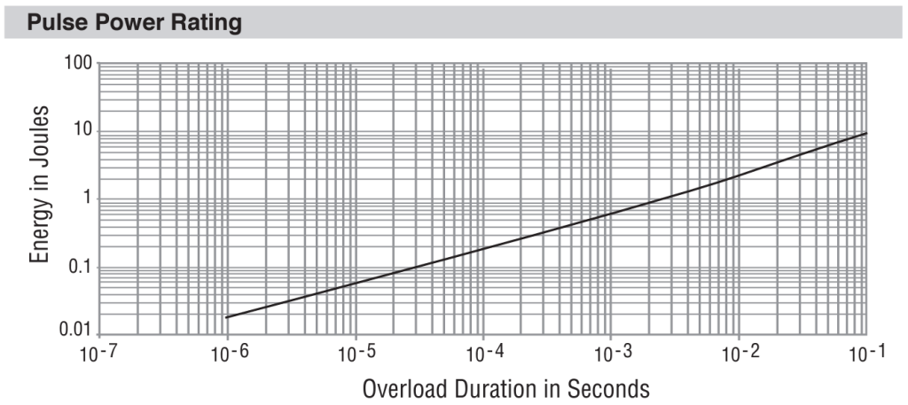
After 1 time constant the bulk capacitance is charged to 63%, after 2 it’s at 86%, after 3 it’s at 95% and after 4 it’s at 98%. Interestingly 5 J is dissipated in the resistor in the first time constant, 4.2 J in the second time constant and 2 J in the 3rd time constant etc. You can see from the graph that these energies are within the specifications of the resistor.
If the output is shorted during the pre-discharge period our poor 40 ohm resistor will have a continuous 50 volts across it. This will dissipate 62 watts or equivalently 62 J/s. Over our 1600 millisecond pre-discharge period the resistor must handle 100 J. If it has a specific heat capacity of 1 kelvin/joule then it’ll heat up 100 kelvin above it’s initial temperature. This is significant but manageable for a situation that shouldn’t occur in the first place. The BQ doesn’t seem to have a protection to realise the output voltage is not rising and to abort the connections process. Looks like a host microcontroller would have to be involved to add this feature. I suppose the main FETs would engage and the short circuit current would trip the output immediately.
I conclude by suggesting that pre-discharge functionality is essentially mandatory if you don’t want to blow up your expensive MOSFETs. Appropriate settings for our BQ here are:
- 1600 millisecond pre-discharge timeout
- Pre-discharge until the output gets to within a 2.5 volt delta from the pack voltage
// This enables the Pre-discharge function (1600 ms, 2.5 v delta)
bms.writeByteToMemory(Predischarge_Timeout, 160);
bms.writeByteToMemory(Predischarge_Stop_Delta, 250);
bms.writeByteToMemory(FET_Options, 0x1D);
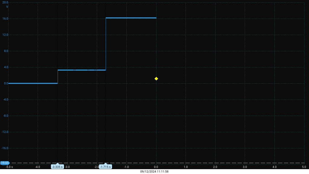
Here’s a picture showing the output voltage of the BMS when switching on across a 10 ohm resistor. It’s being powered from a 16 v source. You can see the pre-discharge period of 1600 ms before the main MOSFETs are switched on.
2.6) Cell balancing configuration
Cells gradually become unbalanced in their state’s of charge (SOC). Even LiFePO4 technology has some degree of self discharge. Assuming a 2-5% self discharge rate per month we can estimate the equivalent self discharge current to be (314 Ah * 0.02) / (30 days) = 9 mA to (314 Ah * 0.05) / (30 days) = 22 mA. Self-discharge depends on:
- Cell Quality: High-quality cells from reputable manufacturers have better electrolyte stability and lower impurity levels, leading to lower self-discharge.
- Temperature: Higher temperatures increase self-discharge due to accelerated chemical reactions. For LiFePO4, the rate roughly doubles for every 10°C increase above 25°C.
- Age and Cycle Count: Over time, degradation of the electrodes and electrolyte can increase self-discharge. Cells with more cycles or older cells tend to have higher self-discharge currents.
- State of Charge (SOC): Self-discharge may vary slightly with SOC. Higher SOC often leads to higher self-discharge due to increased reactivity in the cell.
- Manufacturing Variations: Impurities or inconsistencies in the electrolyte, separator, or electrodes can result in variations in self-discharge rates.
- Environmental Conditions: Humidity and exposure to contaminants can increase self-discharge if the cell’s casing is compromised.
The only way cells can fall out of balance is if their self-discharge rates differ. While we can attempt to maintain consistent parameters across all cells, divergence in SOC will inevitably occur over time. This imbalance progressively limits the pack’s overall capacity, as the cell with the lowest SOC will trigger the undervoltage protection during discharge, and the cell with the highest SOC will prematurely activate the overvoltage cut-out during charging
Lead-acid batteries naturally maintain their own SOC balance more effectively. When individual cells reach a high SOC, parasitic reactions begin to occur, diverting some of the charging current. This process acts like an internal shunting mechanism, allowing the cells to effectively top-balance themselves at high SOC.
If our best LiFePO4 cell shunts 9 mA and the worst cell shunts 22 mA we have a variation of 13 mA. You can therefore see how our balancing circuitry doesn’t need to shunt large currents. The OpenBMS offers balancing currents in the region of 60 mA. Switching these on and off across various cells as required will easily compensate for variations in self-discharge rates.
I read the paper below which claims, “many common cell balancing schemes based on voltage only result in a pack more unbalanced than without them”.
www.powerstream.com wrote an interesting page on LiFePO4 discharge curves for different starting voltages. Here’s one of their graphs:
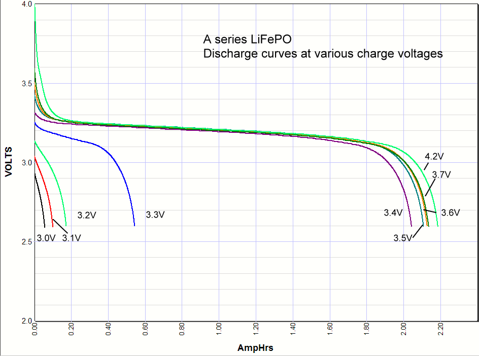
Charging to 3.4 V utilizes nearly all the cell’s capacity without stressing it as much as charging to 3.65 V. The discharge curve is notably flat between 20–80% SOC, meaning that within this range, a small error in voltage measurement can result in a significant error in SOC estimation. At higher SOC (OCV > 3.3 V), the OCV-to-SOC relationship becomes much steeper, making OCV a more reliable indicator of SOC. Balancing is therefore more effective in this region because cells with similar voltages are more likely to share the same SOC. The goal is to equalize SOC, and voltage is not always an accurate proxy for this.
If we balance in relaxed conditions (so the effect of internal resistance is nullified) and we enable balancing only once the lowest voltage cell is greater than 3.30 volts then we should effectively maintain SOC balance. We allow up to 8 cells to be balanced at once limiting our power dissipation.
bms.writeIntToMemory(Cell_Balance_Min_Cell_V_Relaxed, 3300);  bms.writeByteToMemory(Cell_Balance_Max_Cells, 8);
bms.writeByteToMemory(Balancing_Configuration, 0b00000010);

// Disables SLEEP, slow measurement speed when balancing to 1/8th
bms.writeIntToMemory(Power_Config, 0b0010100010110010);
By default the BQ starts balancing once the difference between the highest and lowest cell voltage is greater than 40 mV. It stops balancing once this difference is less than 20 mV. Let’s leave these defaults alone.
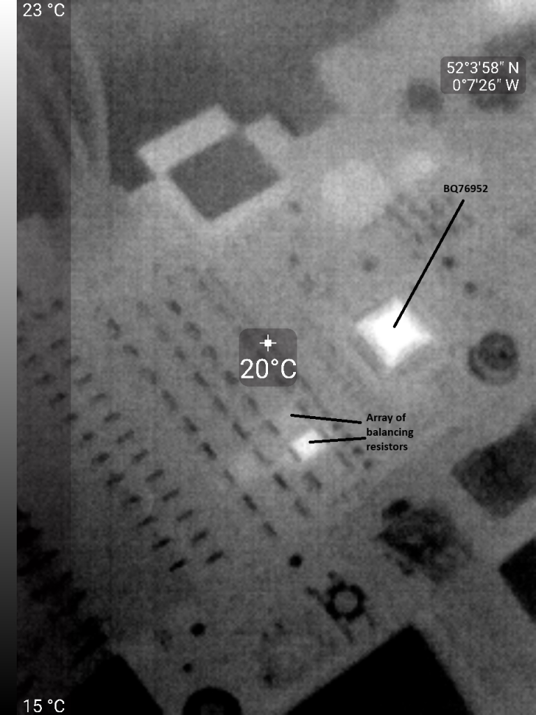
The Power_Config setting needs adjusting somewhat. Without this the BQ interrupts balancing to measure the OCV of the cells so regularly that the average balancing current is compromised. The BQ’s datasheet suggests that it has internal cell balancing resistance typically 28 ohms. Altogether each cell’s balancing shunt resistance is therefore ~50 ohm which leads to balancing currents of ~60 mA. Here is a thermal image showing one of the shunt resistors and the BQ getting warm whilst balancing.
2.7) Exit manufacture mode
The BQ by default is in a manufacturing mode and won’t autonomously enable the FETs unless we exit this mode and give it permissions to enable FETs. This is simple enough to do:
// Exits manufacture mode and allows BQ to enable the FETs subject to protections
bms.writeIntToMemory(Mfg_Status_Init, 0x0050);
bms.setFET(ALL, ON);
3) Estimating SOC
We want to know the SOC of the pack (0-100%) and the remaining capacity (0 – 314 Ah). We can measure the OCV of the pack and we can integrate the current in/out of the battery over a time period to know how the capacity must have changed relative to a known starting point.
Calculating the State of Charge (SoC) of a LiFePO4 battery accurately using voltage measurements can be challenging due to the flat voltage discharge curve. Likewise, integrated current readings rack up cumulative errors over time. Combining these 2 measurements via a sensor fusion approach provides us with a better estimate.
A Kalman Filter is a popular way to achieve the above. The Kalman Gain balances these two steps:
- If the model is more reliable, the prediction dominates. (Rely on coulomb counting more)
- If the measurement is more reliable, the update dominates. (Rely on voltage-to-SOC mapping more)
Let’s define the battery model parameters:
- Nominal Capacity: Total capacity of the battery (e.g. 314 Ah).
- Voltage-SOC Table: A lookup table mapping OCV to SoC for calibration.
- Efficiency Losses: Incorporate charging and discharging efficiencies.
- Measurement error: Higher within flat region of discharge curve
LiFePO4 batteries have this standard OCV to SoC conversion chart:
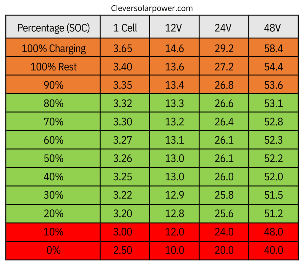
This is fine if there are periods of no load when the open circuit voltage (OCV) can be measured. If there is a continuous load on the battery you never get the opportunity to measure the OCV. You can try to estimate it by subtracting the effect of the current flowing through the internal resistance of the battery. However the internal resistance changes with battery temperature and age so this is not straightforward. When there is a big load on the battery, I think it’s better to rely more on coulomb counting and this can be achieved by varying the measurement noise parameter on the fly.
Here code demonstrating sensor fusion using a kalman filter:
// Battery parameters
const float nominalCapacity = 314.0; // in Ah

// State variables
float SoC = 100.0;                   // Initial SoC in %
float voltageMeasured = 0.0;         // Measured battery voltage
float currentMeasured = 0.0;         // Measured current in A
float SOC_Offset = 0.0;

// Kalman filter variables
float kalmanGain = 0.0;
float processNoise = 0.001;           // Current integration noise
float measurementNoise = 10.0;        // voltage to SOC noise
float estimatedError = 0.2;

float mapVoltageToSoC(float voltage) {
    // Map voltage to SoC using a lookup table and interpolation
    if (voltage >= 54.4) return 100.0;
    if (voltage >= 53.6) return 90.0 + (voltage - 53.6) / (54.4 - 53.6) * 10.0;
    if (voltage >= 53.1) return 80.0 + (voltage - 53.1) / (53.6 - 53.1) * 10.0;
    if (voltage >= 52.8) return 70.0 + (voltage - 52.8) / (53.1 - 52.8) * 10.0;
    if (voltage >= 52.3) return 60.0 + (voltage - 52.3) / (52.8 - 52.3) * 10.0;
    if (voltage >= 52.2) return 50.0 + (voltage - 52.2) / (52.3 - 52.2) * 10.0;
    if (voltage >= 52.0) return 40.0 + (voltage - 52.0) / (52.2 - 52.0) * 10.0;
    if (voltage >= 51.5) return 30.0 + (voltage - 51.5) / (52.0 - 51.5) * 10.0;
    if (voltage >= 51.2) return 20.0 + (voltage - 51.2) / (51.5 - 51.2) * 10.0;
    if (voltage >= 48.0) return 10.0 + (voltage - 48.0) / (51.2 - 48.0) * 10.0;
    if (voltage >= 40.0) return 0.0 + (voltage - 40.0) / (48.0 - 40.0) * 10.0;
    return 0.0;
}

float getDynamicMeasurementNoise(float voltage) {
    if (voltage > 53.1 || voltage < 51.2) {
        return 10.0; // Low noise at high/low voltages
    }
    return 50.0; // Higher noise in flat middle region
}

float SoC_Estimator::updateSoC(float voltage, float Accumulated_Charge) {
    // Predict step
    float predictedSoC = (Accumulated_Charge / nominalCapacity) * 100.0;
    predictedSoC += SOC_Offset;
    predictedSoC = fmax(fmin(predictedSoC, 100.0), 0.0);

    // Update measurement noise based on voltage
    measurementNoise = getDynamicMeasurementNoise(voltage);

    // Map voltage to SoC
    float voltageSoC = mapVoltageToSoC(voltage);

    // Calculate Kalman gain
    kalmanGain = estimatedError / (estimatedError + measurementNoise);
    Serial.print("Kalman G: "); Serial.print(kalmanGain);

    // Update SoC
    SoC = predictedSoC + kalmanGain * (voltageSoC - predictedSoC);

    // Update error estimate
    estimatedError = (1.0 - kalmanGain) * estimatedError + processNoise;
    Serial.print(", Estimated error: "); Serial.println(estimatedError);

    return SoC;
}

void SoC_Estimator::SetSOC(float Set_SoC, float Set_est_error) {
    SOC_Offset = fmax(fmin(Set_SoC, 100.0), 0.0);
    estimatedError = Set_est_error;
}

void loop() {
    delay(5000);

    // Update SoC
    updateSoC(stack_voltage, accumulated_charge);

    // Output SoC
    Serial.print("State of Charge: ");
    Serial.println(SoC);
}
4) Results
The BMS has been up and running for a month now and has been performing ok. I used to be able to start up a large angle grinder before the BMS was fitted but now the BMS trips out. Perhaps the 6 AWG wire in/out of the BMS is inadequate and causing too much voltage drop with the large inrush currents.
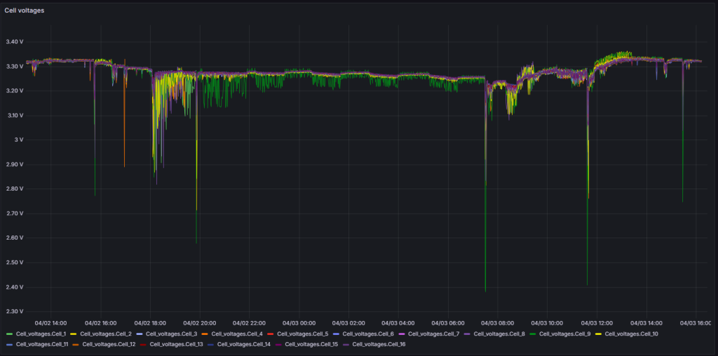
One of the cells appears to sag quite a bit with high current spikes (like attempting to start a large angle grinder)
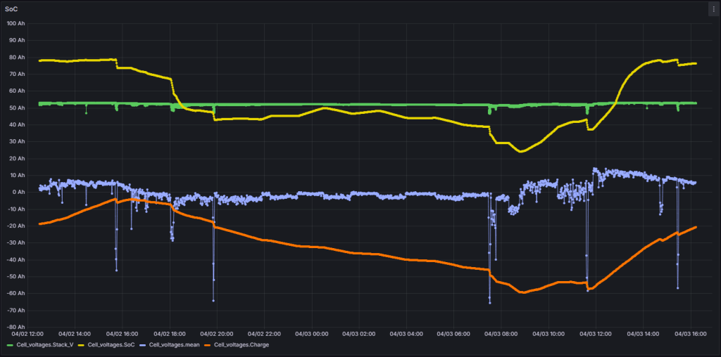
The SOC estimations and charge accumulations appear to work quite well.
Plan
I don’t like this setup. I’m going to design my own BQ76952 based BMS and I have some interesting ideas for this that I will post about once I have made more progress
Further resources
- www.batteryuniversity.com has a lot of useful information on it

Leave a Reply